Which one is the iconic building that inspired a mainstream local musician, turned the sounds of the metal into music and ended up being the subject of an image film? What has been KÉSZ Group's biggest domestic investment to date? Do you wonder how many people were involved at any one time during peak construction hours?
If the above has piqued your interest, all you have to do is register and immerse yourself in our professional content.
How does an old fountain become an award-winning reception building? How did we manage to give Hungexpo, which has more than 50 years of history, a new look? How does a main entrance become an iconic symbol?
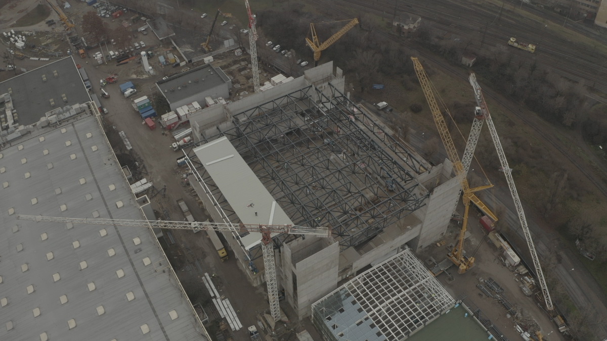
KÉSZ Metaltech experts, engineers and staff participated in the revitalization of the 7800-square-meter HUNGEXPO reception building – among others, in the design of the architect's façade and the construction of the steel structure. The investment can be functionally divided into two parts; the ground floor acts as a receiving distribution area, while there are offices upstairs. In addition to the reception building, countless other areas, centers and halls were also developed – to become one of the biggest jewels of Budapest together. Thanks to the most significant development of the past decades, more than 70 thousand square meters of indoor and 36 hectares of free area renewed by September 2021. The volume of the development is well demonstrated by the fact that 800 people participated in the construction simultaneously during peak time.
HUNGEXPO is the largest investment of the KÉSZ Group at company group level, during which 7 buildings were constructed and renewed. KÉSZ Építő és Szerelő Zrt. was the general contractor, and their work related to building structure (steel and prefabricated reinforced concrete structure) and façade cladding was supported by the member companies of the KÉSZ Group – such as KÉSZ Metaltech Kft., KÉSZ Ipari Gyártó Kft., DVB Kft., Baumetall Kft., bim.GROUP Kft., and last but not least Geolink Kft.
- KÉSZ Metaltech Kft. – Installation of steel structures, manufacturing and installation of industrial and aesthetic façades.
- KÉSZ Ipari Gyártó Kft. – Steel Structure Production.
- DVB Kft. – Manufacture of prefabricated reinforced concrete structures.
- Baumetall Kft. – Manufacture of solid aluminum sheet cladding and Rib-Roof system.
- bim.GROUP Kft. – Design of façade cladding and steel structure.
- Geolink Kft. – 3D geodesy and survey services.
Renovated buildings include buildings A, B and D, newly built installations are buildings D1, D2 and the main building, and the CK building has a small retained part and a bigger newly built part. In terms of quantity, KÉSZ Metaltech Kft. installed a total of more than 3,500 tons of steel structures and more than 45,000 square meters of industrial and 22,000 square meters of aesthetic cladding under the project.
CK
The building is composed of four parts: head building, hall part, foyer, conference part.
The length of the building is 186 meters, the maximum width is 61 meters. The entire building has a floor area of more than 22,000 square meters; the remaining renovated building part has a floor area of: 5,252 square meters; while the new part of the building is 17,193 square meters. During the construction of the building structure, a total of 12,700 cubic meters of concrete and 1,390 tons of reinforcement steel form the monolithic reinforced concrete framework of the facility, in addition, more than 1,000 tons of steel structures were installed. The works of the newly built part of the CK building were carried out by KÉSZ Metaltech.
Our tasks: In addition to the installation of 1.169 tons of steel structure, the installation of the industrial and aesthetic cladding of the hall and the cladding of the interior spaces.
Pavilion “A”
Pavilion “A” is the largest pavilion of Hungexpo with a gross floor area of 21,311 square meters. The exhibition space is 19,480 square meters and its height is 6.9 meters.
Our task: replacement of the façade sandwich panel cladding and construction of external suspended ceilings.
Pavilion “B”
During the renovation of the pavilion, which has an exhibition space of 6,500 square meters (gross floor area 8,000 square meters), the exterior façade was completely renewed, the doors and windows have been replaced, a new fire alarm system has been installed in the name of safety, the building has been given a new resin coating, the visitors' sanitary blocks have been completely renewed, new modern LED lighting has been installed, and new engineering provides cooling and heating in the pavilion.
Our task: the renovation of the exterior façade cladding and the construction of the engineering space.
Pavilion “D”
Pavilion “E” is connected by a link corridor to Pavilion “D”, which has a 5.127 sqm exhibition space (gross floor area: 5,460 sqm). 1,886 square meters of new sandwich panels were added to the building, which has a ceiling height of 6.85 meters.
Our task: renovation of the façade cladding of the hall.
Main building “F1”
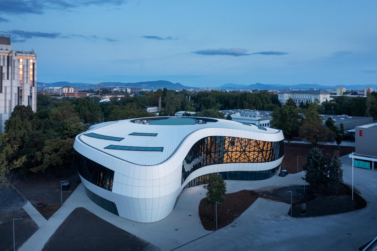
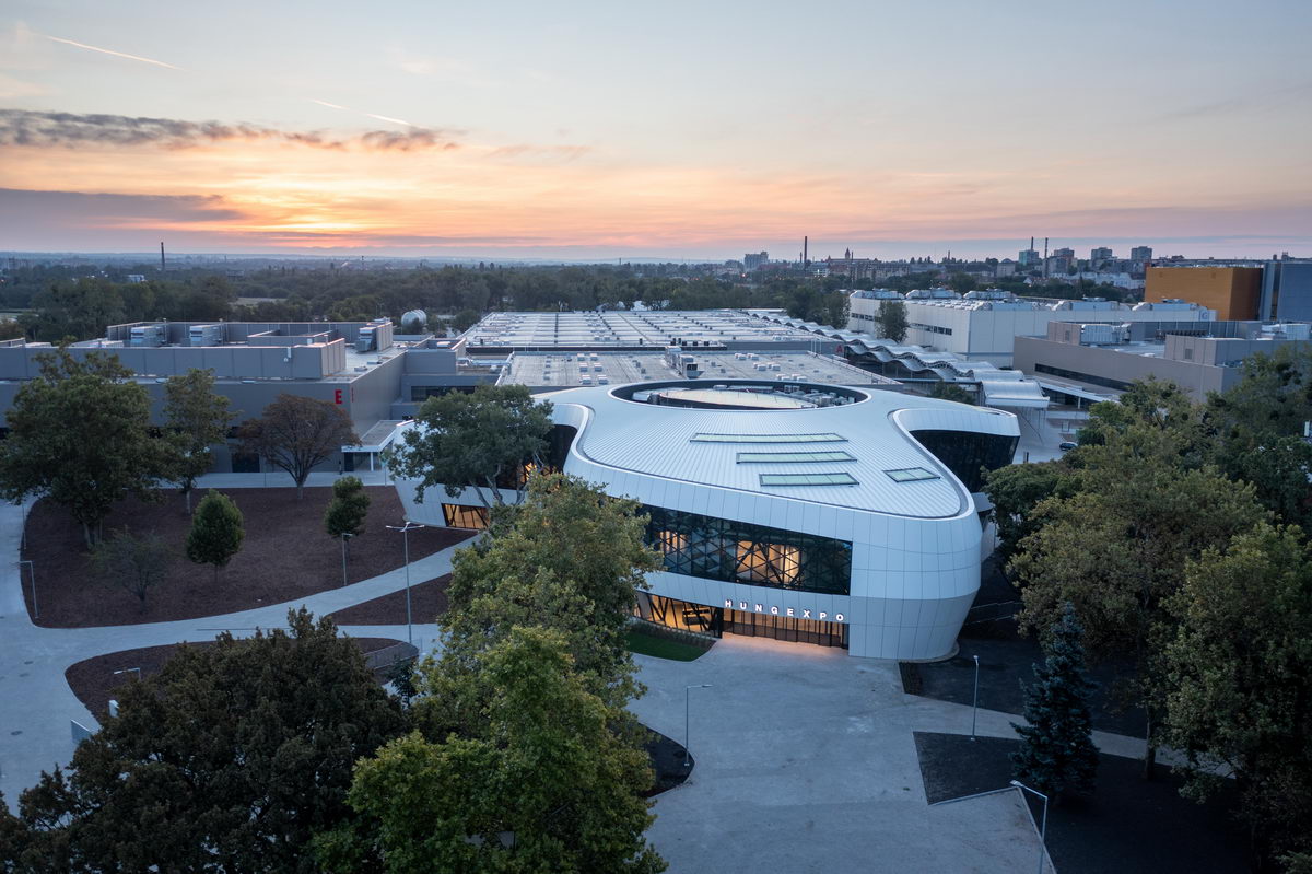
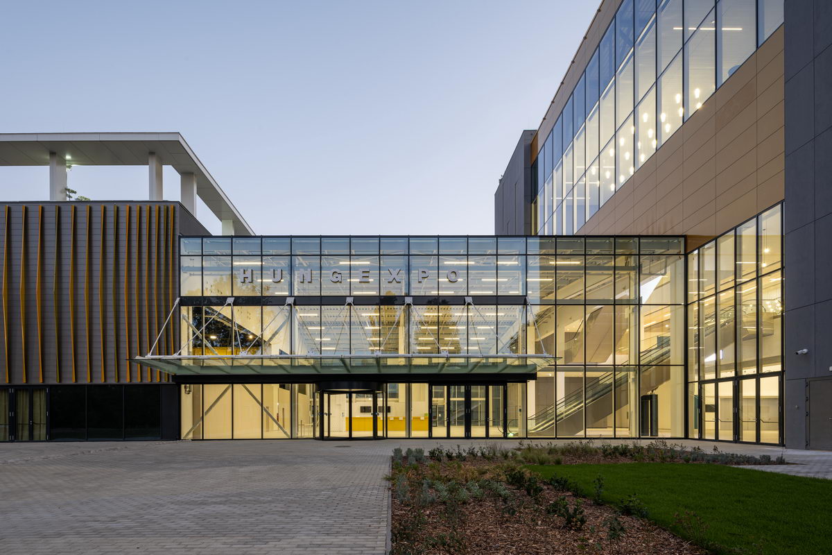
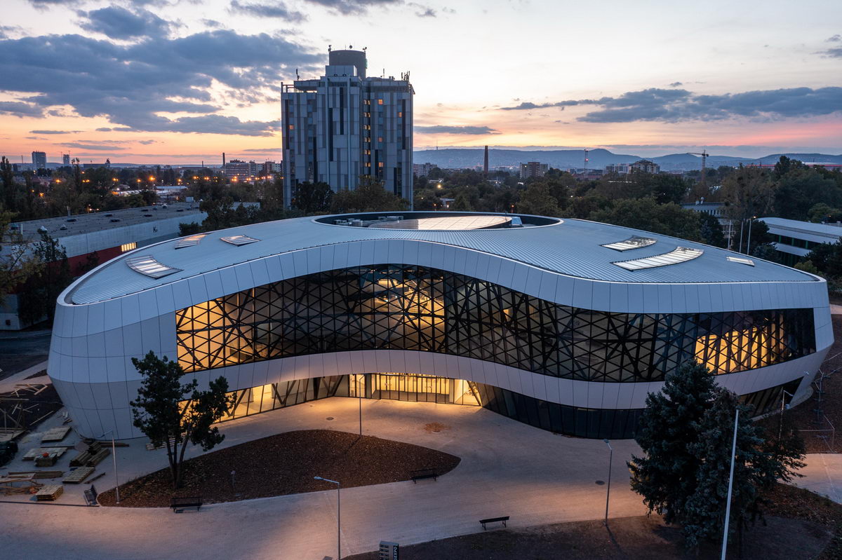
The new 7,800-square-meter reception building “F1“, built at the site of the old fountain and pool, will serve as the main entrance to HUNGEXPO and as a visitor distribution building in the future.
KÉSZ Metaltech Kft. was recognized for the design, manufacture and construction of the building frame and façade cladding of the HUNGEXPO reception building, on the ALUTA (Aluminum Window and Façade Association) tender in 2022, in the major project category, receiving the ALUTA Award of Excellence.
Form and Requirements
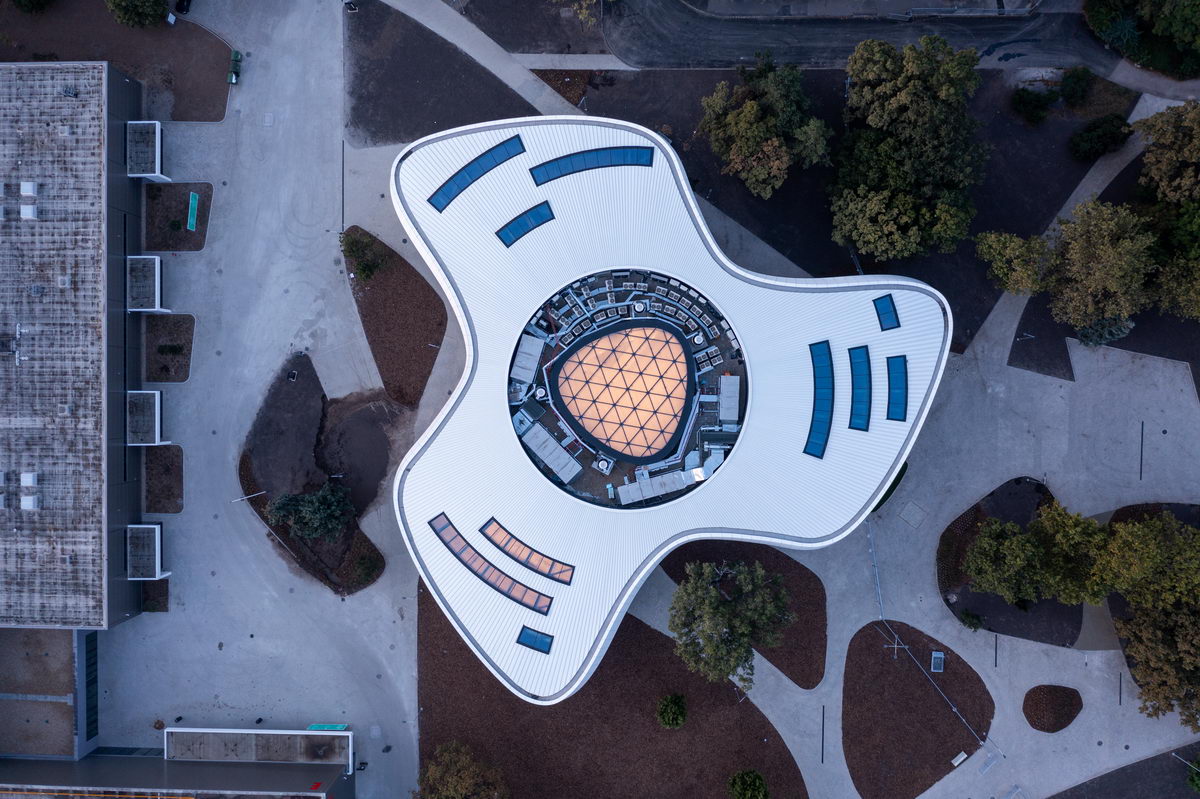
The old development plan of HUNGEXPO, founded in 1967 in the X. district of Budapest, was the creation of a new, up-to-date, modern reception building. The revitalization of the Expo Park Ltd. investment in from 2019 to 2021 created the building that became an iconic symbol of the area hosting international exhibitions. The gross area of the building is 6,300 square meters and includes the ground floor, the first floor and the second floor. The building can be functionally divided into two parts; the ground floor acts as a receiving distribution area, while there are offices upstairs. The building block consists of three building parts (propeller blades) and a distribution space (circular shapes connecting the former).
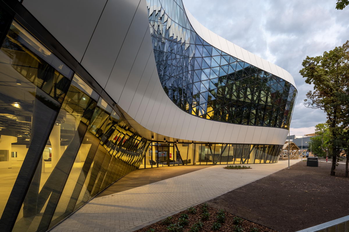
The characteristic design of the body, form and mass was born on the table of Finta Studio, and the main motif was the so-called triskelion, which is a three-axis symmetrical shape. The triskelion-shaped architecture balances the lean pavilion world and emphasizes the arrival area as an organic, contemporary architectural element. The park, with its valuable 80 to 100-year-old large-leaved trees and groups of trees, has been given a prominent role in mass formation. The organic body, which blends into the environment, was created by bypassing and protecting the trees in the park. It was an important task to plan the movement direction of visitors so that the house could serve up to two parallel events.
In the multivariable formula of differentiable movement directions, dominant foci, positions of trees and skyscapes, they searched for a geometry with symbolic power. The silhouette forming the triskelion is an ancient symbol of cyclicity, continuity, progress and eternity. Thanks to the smooth, clean, curved and dynamic façade and the effects of light and shadow in its bays, it faces its surroundings with a diverse face from every point of view. An important stipulation in the construction of its façade grid was the elimination of technologically expensive, double-curved façade elements.
However, in order to create the façade form, the boundary walls had to be arranged along radii, from which there are typically 6 centers per unit. The mass of the building is set to its final size by the bounding plane of the roof, which is the intersection of a spherical surface, paying attention to the balance of the building.
During the review of the building's design, many models were created, through which KÉSZ Group's strategic partner, bim.GROUP, was able to examine the effect of the geometric simplifications and manufacturability criteria for the reinforced concrete and steel structure. Due to the shape of the building, even small simplifications caused a huge change and greatly influenced the location and design of the underlying structure. When creating the final form, it was necessary to take into account the properties of the complex support structure and the constraints of the cladding layering,
It was important that the façade panels reproduce the surface formation dreamed up by the architect in every case. The models were created using parametric modeling during the design of both the support frame and the façade cladding. In any case, it was beneficial that the steel structure and building envelope design was carried out within bim.GROUP Kft., too, and that the design was carried out on the same software platform in both offices (Rhinoceros, Grasshopper).
The shape of the building was no longer an issue, but its line was even more so. The graceful and curved shape of the façade is brought to life by the panels. Therefore, the panel allocation was a cardinal aspect, which had to take shape before the design of the frame, i.e. the load-bearing structure. The plane created by the allocation defined the boundaries of the outer plane of the steel frame structure. Before choosing the final allocation, several formal plans were created, processed with panels with flat and curved surfaces.
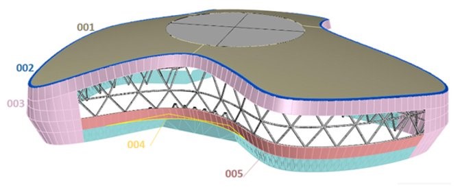
According to the final panel distribution with a curved surface, the building was divided into 5 characteristic parts. This division was made due to the definition of the main façade areas. Each area has its own special part, which justified the demolition. Additional areas were also defined within the units, and as a result, characteristic building junctions were created, which helped to localize the technical tasks to be solved.
001 | Roof Covering
002 || Gutter
003 || Façade Cladding
004 || Turning Horizontal
005 || Under a Glass Façade
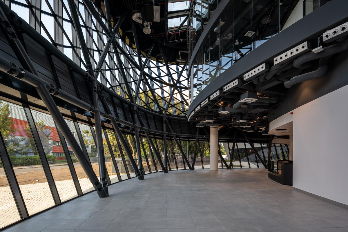
Frame in the Foreground: Manufacturable Design
When designing the steel structure, 3 simple things had to be met: the frame must be statically verifiable, the structure must be visible and aesthetic, and it has to be able to receive the casing.
The boundaries and limitations set by the side wall pipe and the open sections of the roof were quickly recognized, and by focusing on their solutions, the maximum tolerances determined by the stratification could be observed. The connections created shapes that rotated in space, which, connected to the curved elements, gave the opportunity for mistakes. The tolerance of 20 millimeters of the layer order was also a close criterion.
- Statically Verifiable Frame
In the design, the engineers used parametrically prepared steel-framed modeling, so the changes were visibly followed and controlled during the construction of the model, and the steps could be visualized well and almost instantaneously. When clarifying the sizing principles, section types and their malleability were also considered. The selection of the final sections had an impact on the structural engineering, and the design of the nodes had to examine the principles of manufacturability. In addition, aesthetic requirements also influenced the design.
- A Visible and Aesthetically Pleasing Structure
It was necessary to find architectural solutions for mechanical connections according to previous experience. It was necessary to establish connections that pleased the eye and were uniform throughout the house, not changing. Although the expectation was a hidden connection, it was still possible to find a look and aesthetic design that provided a small number of fasteners and managed to keep the connections flat.
Taking manufacturability aspects into account, it was necessary to have many of the same elements and few individual elements. Besides, angular rotations had to be minimized. Aesthetic considerations raised mounting issues: the size, type and location of fasteners are decisive, since the structure can be mounted only if the connections perform their function, while the goal was to keep on-site welding to a minimum.
- It Has to Be Able to Receive the Cladding
At the modeling stage, the receiving structures of the cladding elements, that is, the secondary structural elements, have already appeared as the main task. The construction of the layered façade cladding on the inner side plays an aesthetic role. This was the need to keep in mind. In addition to the apparent internal steel structure, the inner plate cladding of the façade was also a visible surface, so the secondary structures had to be uniform. As a result of the two intersecting planes formed in the lower load-bearing layer of the arched sheet casing, secondary supports in the shape of "cottages" were formed, which were connected by pipe sections to the load-bearing frame, which also had a tubular structure.
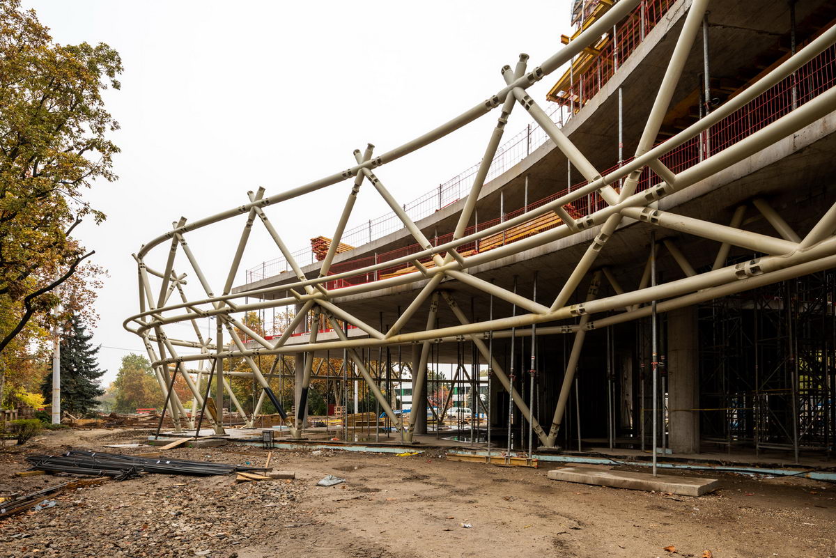
Frame Construction
High-precision production of steel structures was ensured with a geodetic presence, however, ensuring mounting tolerances and shape accuracy also required geodesy. Each millimeter of displacement compromised the shape of the structure. The accuracy of the sidewalls was checked on site with a system that could be measured back several times, which also provided control over the placement of the entrenched slab connection elements and the accuracy of the steel structure.
In terms of the assembly order, starting from the receiving structures that will be placed in the reinforced concrete structure, the frame construction was carried out on a level-by-level basis. The starting point of structural construction in all cases was the same at all 3 construction levels. The façade steel structure is enclosed by level, so it was also possible to check the shape accuracy with measurements. The construction of the next level could only proceed after a form adjusted for possible gaps placed in the right place. The roof structure could start after the repair of certain sections of the rim ring.
From the point of view of roof structure construction, the triskelion figure proved to be excellent. The steel structure and the reinforced concrete structure of the central mechanical space in 3 characteristic internal arched places were so close to each other that it was possible to take advantage of this small distance to build structural radial supports to brace the upper, "roller coaster"-like ring. The radial main supports were made in one and two pieces, respectively. The side supports could be installed without problems as a result of precise structural manufacturing and assembly.
Cladding on the Roof and Façade
The cladding system has been refined at an early stage, and the layered design of this system meets the requirements of the building.
- Load-bearing Profiled Sheet
- Thermoprofile Hat Profile Thermal Insulation
- Rib-Roof System
On the main supporting structure, the load capacity is provided by a 150-millimeter load-bearing trapezoidal plate located on the roof. In order to reduce thermal bridges, perforated Z-shaped supports have been installed between the lower load-bearing trapezoidal plate and the watertight casing, which also provide the connection between the two layers. With this perforated profile, the formation of point thermal bridges has been reduced to ensure the expected heat transfer value on the entire roof structure and subsequently at the side wall of the building. These Z profiles were then attached to a support structure profile in another direction, which could receive the clips needed to secure the Rib-Roof plate.
The layer order of the roof structure contains these main elements, but a unique sheet covering has been placed on the side wall on the inner side, which is the company’s own developed product. The façade cladding is modelled on the roof layer order, taking advantage of the unique feature of the Rib-Roof plate. All this, by attaching it to the corks, allowed a solid aluminum element called rainscreen element on the outside of the casing to cover the watertight plate plane. A uniquely designed and manufactured internal aesthetic sheet covering was made on the inner side, adapted to the pattern of the load-bearing trapezoidal plate. This sheet covering is fixed on the façade support auxiliary profiles. On the outer side, a solid aluminum element mounted on a solar mount, fixed on an aluminum profile row, was placed. The nodes formed on the house are adapted to the design of the building.
To work out the cladding details in the façade division, we returned to the division of the form search:
- Roof covering
- Gutter
- Façade cladding
- Turning horizontal panel surface
- Area under the glass façade
This division allowed nodes to form according to the pace of construction and the order of priority – a total of 37 base nodes. It was necessary to bring forward the nodes of related glass structures, since this area also determined the works of other contractors.
During the solution of the tasks, it became necessary to build a full, real-size mock-up, on which bim.GROUP was able to test the concepts created on the drawing board, so that it can be screened and corrected before any design errors that may arise occur on the spot. Certain parts of the steel structure were pre-assembled in a manufacturing environment. The creation of the sample wall also clarified a lot of construction processes, especially in the field of cladding construction. Thus, the design was able to incorporate the experience in time, for which the modeling built with the previously mentioned parametric (algorithmic) design approach was of great help.
During the design phase, the mock-up was transformed several times, and it was necessary to take into account the tolerances of the different layer order levels and the mounting tolerances. After the preparation of the plans, the changes documented during the assembly processes were returned to the sample wall model in quasi-real time. And the changes made to the model of the sample wall were only made to the model in a final state.
In addition to modeling and production plans, assembly plans also had to be produced. Due to the unique design of the building, the traditional assembly plans were not applicable here, as the shape cannot be traced with a typical plan projected on a plane, so the work was carried out using covers. And these covers had to be handled together with the production plans. To support the assembly, the assembly plan of several parts was also needed, these were not nodal plans, but assembly instructions for further extended or sub-assemblies of the assembly units. Although the curved surface was made with compensating planes in the inner layers, the tolerance zones had to be maintained.
The design of the single and double curved solid aluminum panels covering the façade was a unique process, and several trial productions took place until the panels took their final form and were ready to be installed. The accuracy of the substructure supporting the surface was solved with a system resting on 2-way adjustable solar supports, so the cover could be adjusted with an accuracy of almost 0 millimeters, for which geodetic scanning and measurement were applied. The placement of the solid aluminum cladding plates has already been done in the previously leveled and designated places, with accuracy provided by on-site measurements and possible manufacturing errors eliminated.
The load-bearing plates of the roof and side walls were both made of plates cut to size. Due to the shape of the building, all the side wall plates had to be adjusted not only to their length, but also the side size of one of them had to be reduced – i.e. it had to be cut to shape to fit the surface created with the secondary steel structure. This affected both the cover and load-bearing plates. The main problem was the double fastening and surface contact, which we were able to solve with the cottage-shaped secondary profiles.
Overall, it can be said that the HUNGEXPO main building presented KÉSZ Group with great challenges in terms of design, production and installation. The key to overcoming these challenges was our experienced professionals, skilled physical workers and specialized engineering team. All of our employees worked day after day with innovative thinking, pushing the limits of their knowledge, so that finally this fantastic building was born as a result of the coordinated performance of the team. The introduction of the new technologies used here will also provide a useful basis for the planning and construction of similarly complex buildings in the future.